The Radio Control Club of Detroit
An AMA Gold Leader Club |
The Radio Control Club of Detroit
|
|
|---|
| AMA Chapter # 368 | An AMA Charter Club Since 1953 |
IMAA Chapter #206 |
Schedule |
|||||||||
Events Only |
News Archive |
RCCD 2011 Scratch Build Project - Tips
Please send tips to the Webmaster. As you are building your Stick, if you have a good idea to share with the other builders, send a picture, a sketch, or a description and we'll post it here.
|
Workshop Tips: Work Surface Preparation: Some useful Q&A (from e-mails to Pete): Q1: From your experience, is there a recommended engine for this size Plane? I thought I heard that a 60 size plane, usually needs a 60 size engine. Q2: I see from the picture on the RCCD Home page that the engine is rotated 90 degrees to the left or Starboard side, Why? What advantages does this offer, vs straight up? Q3: If the engine is rotated, is the fuel tank also rotated 90 degrees in the same direction? Q4: The fuel tank floor board is not shown, is there a recommended position, height that it should be? Q5: 5th- The wing length is optional to the builder, by making it longer I would get more surface area, will this make it fly better? Would the added weight (I'm not sure how much) make a difference in engine size? Q6: (a) I noticed in the full size plans that the push-rods criss cross in the middle of the fuselage. I also noticed that the plywood inserts (elevator) call out for the criss cross. What would happen if I did not criss cross them but took them (push-rods) straight back from the Servo to the control surface. I would move the elevator insert to the other side. Q7: The engine cowling we make up later, or am I missing something.
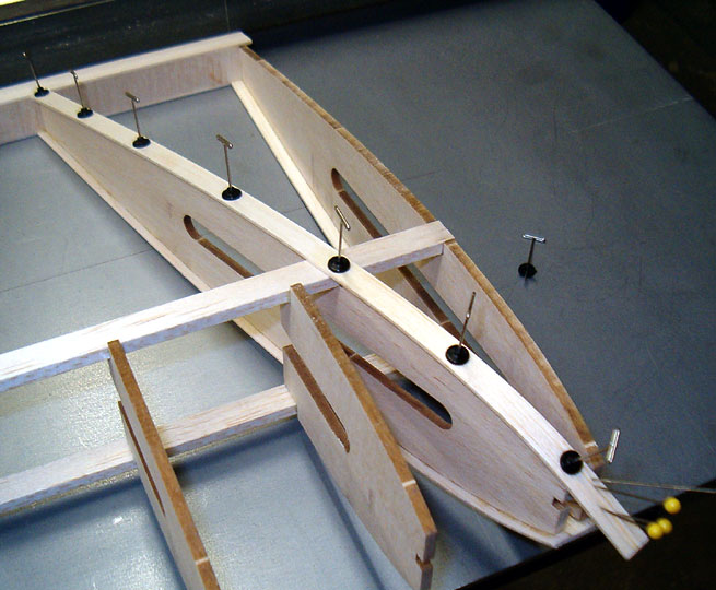
Pin Clamps - From Snapshot At the ground school, Don brought up using pin clamps in construction. This information may be helpful: For wood models there is nothing simpler or more basic than pins. There are a variety of types but the kind most modelers prefer are T-pins. These come in a few sizes. Usually the pins are put directly through the piece of wood being held in place. In some cases they may be criss-crossed over pieces rather than through them. In addition to pins I use a product made by Rocket City called Pin Clamps (these are now sold by Nelson Hobbies*). These are small plastic disks that fit tightly onto a pin and are used to spread out the clamping pressure. I really like them.
* From Maverick - Nelson has now closed. I have found another place to get these Pin Clamps ( address below). For smaller models, such as rubber powered airplanes, dress makers pins are more appropriate because they have a smaller diameter. Pins do not stay sharp forever. It is a good idea to buy new ones every so often. I can not say how often because it depends on how many kits you build, but they are inexpensive enough that you can dump your entire supply and buy new ones when needed. More thoughts on Wing Span (WS) Q8: I'm going to start building the wing soon and would like your input on the span I should go with, don't know if the shorter or longer span would be better. My thinking is the longer version. I really don't care if it weighs a little more. A8: This project is about learning and trying stuff, so I am not going to recommend a wing span for you; rather explain what to expect and let you make an informed choice. Rattlesnake may have additional thoughts on this. Here's how to look at it: The extra bay on each wing will not add much weight at all. At a guess, about 4 oz. So to look at two possibilities. 60.75" and 67"......
Wing Loading chart:
So both still fall within the "sport scale, sport aerobatic" wing loading, but the 67 inch wing span is closer to sport flyer and therefore will be able to fly a bit slower before it stalls. So what else to consider?
A couple of additional comments regarding the Ugly Stick design (from Rattlesnake). The above explains the technical side of the wing options, and the list of considerations regarding the plane is spot on. As is clearly pointed out in his technical comments regarding the wing spans and wing loading, the overall numbers or results all fall within the sport flying classification, as the plane was originally design to be. The semi-symmetrical rib section also plays an important part in it's flying abilities. The original design of the airplane is basic and forgiving allowing for the different modifications. The wing span options give the individual builder the latitude build the plane and to say, " it's to my specifications, design and look". An important factor is to make sure the plane's CG is balanced correctly. (This remains the same as long as the wing chord remains the same. 11.2" from the firewall as long as you did not alter the firewall location! You can always figure on a CG to be 25% to 30% back from the leading edge on a straight wing like this. Or use the CG calculator in our main Tips and Hints page for any wing, even swept, tapered and biplane wings.) Do your thing, and have fun doing it. Thoughts on Balancing your plane: VERY IMPORTANT - The CG dimension given in the instructions will result in a tail-heavy condition. DO NOT USE 11.20 INCHES FROM THE FIREWALL. For your first flight, use 25% of the total chord. The Stick wing has a constant chord, so measure the distance from the leading edge (LE) of the wing to the trailing edge (TE) of the aileron; calculate 25% of this; place two pieces of masking tape on the wing on either side of the fuselage at about this (25%) distance back from the LE and accurately mark the 25% location on the masking tape; Also mark the 30% location for reference. Depending on your aileron width, 25% and 30% should be about 3.5 & 4 inches back. I try to avoid adding weight to balance my planes at all costs. For glow planes I locate the receiver battery pack, the rudder & elevator servos, and cowl after I have everything else installed, but before I start the covering. I temporally place them then lift the plane with a finger on each 25% mark. I move the items around until I get the plane to balance. If the plane will be tail heavy, I install the battery as far forward as the design allows. Even in the tank area or cowl if there is space. The rudder & elevator servos go as far forward in the wing opening area as possible. If still tail heavy, I will add spacers between the firewall and engine again if the design allows. If all this fails to achieve the desired balance, a heavy spinner nut can sometimes help. To correct a nose-heavy condition, rudder & elevator servos can be mounted near the tail, either on the surface, or behind a hatch. The battery pack can be located in a belly hatch between two formers. If it is not too late, you may be able to mount the engine as far back on the engine mount as possible (but make sure there is clearance for fuel hoses. You may also be able to switch from a trike gear to a tail-dragger configuration. This eliminates the nose wheel weight and adds tail wheel weight. For electrics, in addition to the above, the main power battery pack can usually be moved fore and aft to achieve balance. The addition of dead weight is the last resort. A nose-heavy plane flies poorly. A tail-heavy plane flies once! For your first flight avoid the condition ... "A tail-heavy plane flies once!". That is why a 25% balance point is suggested. But after the first flight don't then ignore the first part of the adage .... "A nose-heavy plane flies poorly". A nose-heavy plane will stall at a higher speed, have to land faster, will change pitch a varying speeds, will not roll as straight as it should, will require more down elevator when inverted, and generally not be as pleasant to fly as a correctly balanced plane. Take the time to get the balance right. This can only be done making slight adjustments and checking the results. Ask for help if needed.
|
njh